
I2C is normally thought of as being a straightforward and easy-to-use interface, but there are some pitfalls that can catch the unwary. In this post I’m going to explain one of them and give some practical advice that will help you avoid being caught out.
What is I2C?
First of all, to re-cap: I2C (Inter-Integrated Circuit) is a two-wire serial bus designed by Philips Semiconductor (now NXP) some 40 years ago. As the name suggests, its main purpose is to act as a communication path between ICs on the same circuit board. I2C has become very popular and is widely used to interface low-to-medium-speed devices such as EEPROM, temperature sensors, and the like with microcontrollers and Systems on Chip.
I2C has two signals, clock (SCL) and data (SDA) which are wired between the master – usually a processor of some sort – and all the slave devices (for example: EEPROM, sensors, etc.) on the bus. Both the SCL and SDA lines are bi-directional so they can be driven by the master or any slave device. Only the master normally drives the clock (that’s a slight simplification), but slaves are of course expected to drive the data signal when the master reads from them. In fact, both SCL and SDA are “open drain” signals used in a wired-OR configuration where a low (0) signal occurs when any device on the bus actively pulls the line low, and a high (1) signal is the passive state when no-one is driving the line. The passive state results in a high signal because both the clock and data lines must be fitted with pull-ups.
The I2C specification describes how the master addresses a particular slave and sends and receives data from it. This Saleae Logic trace shows what a typical multi-byte read transaction might look like:
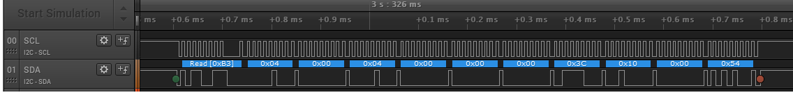
The first step in that process is for the master to make sure the bus is not already in use, which it does by monitoring the state of the SCL and SDA signals. Only when the master can see that the bus is not busy can it start the transaction (shown by the green dot on the trace). One condition that tells the master that the bus is busy is if either SCL or SDA are being pulled low, since the idle state requires both signals to be high.
How can I2C lock up?
Now to the problem: in some circumstances the I2C bus can “lock up” in a busy state which prevents the master from ever being able to start a new transaction. Since the master controls the transactions on the bus, this means nothing else can happen after the lock-up occurs. Obviously, this could be a show-stopping condition for any system that depends on the I2C bus to scan sensors or read from EEPROM, for example.
That raises several questions including:
- what causes I2C lock-up?
- how can lock-up be detected and recovered from?
- how can lock-up be prevented?
To understand how the I2C bus can lock up, it’s helpful to think of things from the perspective of a slave device. The slave must monitor the state of the clock and data signals, and in particular must look out for transitions of either signal which may indicate the start or end of a transaction or the need to clock data in and out. All will be well provided the slave device sees the same series of transitions that the master generates, assuming they conform to the I2C protocol specification.
But if there’s some noise or interference that causes an unwanted extra transition or masks a wanted transition, the slave can get out of step with the master. For example, if the master needs to transfer one byte of data from the slave, the slave is expecting to see a specific number of transitions on the clock signal to clock each bit of the data out (and to provide an acknowledge signal). If a clock edge gets “lost” somehow, the slave device will never finish transferring the data and may end up continuously pulling the data line to an active low state.
Now the master might “think” that the transaction has finished, so won’t issue any more clocks, but the slave “thinks” the transaction is still in progress so will keep the bus in a busy state. While the bus is busy, the master can’t generate any more clock transitions. While there are no clock transitions from the master, the slave won’t let go of the bus.
Another situation where lock-ups might occur is during start-up when i/o signals from the master might have glitches or other unexpected transitions before they are stable. If an I2C slave device is monitoring the bus before the master brings the clock and data lines into the right (passive) state, this can cause the I2C bus to be locked before the master starts the first transaction.
Finally, even if the bus is very well-behaved and doesn’t suffer from noise or glitches, lock-up can occur during software development. Let’s say you’re testing and debugging a system using I2C and your software crashes or hits a breakpoint while an I2C transaction is in mid-flight. If you simply reset the CPU or re-start the software, the I2C slave will never see the end of that transaction so the I2C bus will be locked when the software re-starts.
How should my design handle lock-up?
So, I2C lock-up is definitely “a thing” in practice as well as theory. What can be done about it?
The first approach is prevention. This largely depends on good electronic design to minimise the chance of noise and glitches. For example, this might include:
- using “strong” pull-ups to speed up the rising edge of the SCL and SDA signals
- using i/o signals on the I2C master that have default “high” state, possibly with pull-ups, when the master comes out of reset
Software can sometimes also play a role: if the software running on the master has to configure the signals used by the I2C interface, be careful to make sure that the configuration sequence can’t introduce any unwanted transitions.
Despite the best intentions to prevent lock-up, it’s good practice when designing a system based on I2C to assume that lock-up can occur and to make the system resilient by detecting and recovering from it. This is usually a burden placed on the master software, although hardware design can also help out.
The basic principles here are:
- always implement a well-defined time-out period when waiting for any I2C event
- if a time-out occurs that might indicate a lock-up, either reset all the slave devices or issue a sequence of at least ten clock cycles on the I2C SCL signal
All production-quality I2C device drivers should support time-outs when waiting for I2C events such as gaining access to the bus and completion of data transfers. Depending on the design, the I2C master may include a dedicated controller that might have hardware support for time-outs, in which case the driver should use it. Otherwise, or if the master uses “bit-banged” discrete input/output signals to drive the I2C interface, the I2C driver might have to use software time-outs. Either way, if a time-out occurs it could mean that the I2C bus has locked up and some recovery action needs to be taken. (One exception to this is if you’re dynamically “probing” the I2C bus to discover what devices are on it, but that is not very typical in production software for an embedded system.)
The best recovery action will also depend on the hardware design. In the best case, the hardware will allow each I2C slave device to be reset by the software on the master. For example, this could be done by toggling one or more discrete output signals. Otherwise, the best recovery action is usually to force a series of at least ten clock pulses out on the I2C clock signal. Why ten pulses? Because typically it takes nine clock pulses to clock one data byte in or out of a slave device, after which it will normally release the bus.
If the hardware has a dedicated I2C controller, generating this sequence of pulses might not be straightforward because the controller hardware might not give you direct access to drive the clock signal. In that case, you may have to re-configure the I2C clock pin so that it can be driven as a bit-banged discrete output. In any case, make sure that the clock pulses are generated at about the right frequency (e.g. 100 kHz or 400 kHz), and definitely no faster than the maximum clock rate of any device on the bus.
How about a real-world example?
Here’s a typical piece of code taken from a system I worked on recently to generate this clock sequence. The master was an NXP KL17 micro-controller, which has a built-in I2C controller. The KL17 I2C controller doesn’t let software drive the clock directly, so I had to configure the SCL signal as a bit-banged output for the recovery sequence, then re-configure it to be used by the I2C controller for normal operation:
/**
* @brief Definitions
*/
#define I2C_RECOVER_NUM_CLOCKS      10U     /* # clock cycles for recovery  */
#define I2C_RECOVER_CLOCK_FREQ      50000U  /* clock frequency for recovery */

#define I2C_RECOVER_CLOCK_DELAY_US  (1000000U / (2U * I2C_RECOVER_CLOCK_FREQ))

...

/**
* @brief  Recover I2C from potential lock-up condition
*
* Issue a sequence of ten clock cycles on the I2C SCL i/o pin, without regard
* to the normal I2C protocol.  This is intended to recover from a lock-up
* condition whereby a slave is driving SDA low because it is stuck in mid-
* transaction.  This condition should not occur during normal start-up from
* power-up, but it may occur if the software is re-started (e.g. during a
* debugging session).
*/
void i2cLockupRecover (void)
    {
    /*
     * Configure SCL pin as GPIO.
     */
    PORT_SetPinMux (I2C_SCL_PORT, I2C_SCL_GPIO_PIN, kPORT_MuxAsGpio);

    /*
     * Initialise pin direction and initial state (high).
     */
    const gpio_pin_config_t pinConfig =
        {
         .pinDirection = kGPIO_DigitalOutput,
         .outputLogic  = 1U,
        };

    GPIO_PinInit (I2C_SCL_GPIO_PORT, I2C_SCL_GPIO_PIN, &pinConfig);

    /*
     * Synthesise several clock cycles; leave i/o pin high.
     */
    for (unsigned int i = 0U; i < I2C_RECOVER_NUM_CLOCKS; ++i)
        {
        delayUs (I2C_RECOVER_CLOCK_DELAY_US);

        GPIO_PinWrite (I2C_SCL_GPIO_PORT, I2C_SCL_GPIO_PIN, 0U);

        delayUs (I2C_RECOVER_CLOCK_DELAY_US);

        GPIO_PinWrite (I2C_SCL_GPIO_PORT, I2C_SCL_GPIO_PIN, 1U);
        }

    /*
     * Reconfigure i/o pin as I2C SCL.
     */
    PORT_SetPinMux (I2C_SCL_PORT, I2C_SCL_GPIO_PIN, kPORT_MuxAlt4);
    }
Another piece of good practice is to always issue the “lock-up recovery” clock sequence when the master software starts up. Then any potential glitches during power-up won’t cause the bus to lock up before things get properly started. This technique can also make life much less frustrating when you’re re-starting a system without power-cycling it – for example, during a debugging session.
Here’s a trace showing the software-generated recovery sequence produced by the code above when the system starts up, shortly followed by the first “real” I2C transaction:

If you’re planning to use I2C in your embedded system design, or are already using it, I hope this has given some insight into the potential for lock-up and how to avoid it, or detect and recover from it. May all your designs be lock-up free.


congratulations for the post, helped me a lot.
Thanks, I’m glad you found it useful.
Thanks, for such nice post.
Thanks, glad you liked it.
If you have devices from which multiple bytes can be read back is it worth clocking out further?
Good question. I’ve found that clocking out at least 9 bits is enough to resolve/prevent lock-up in the systems I’ve worked on. The sequence ends with an I2C STOP condition which should tell any slave device that the transfer has ended even if it would normally continue with more bytes.
This is a valid question. I find that clocking out until SDA is high, then sending STOP is sufficient. This way, the bus can be unstuck in any number of clock cycles. There is no guarantee that after 9 cycles the “stuck” device will not be pulling SDA low therefore preventing you from sending STOP. And in the case of sequential reads, the device will not finish the transaction.
Thanks for this information. Do you have any suggestions on how to intentionally cause the lock-up to ensure the MCU can correct it with the 9 clock pulses?
Thanks for your question, Aaron. I’ve found that configuring the system to run frequent I2C transactions and then temporarily shorting the SDA line to 0V (for example with a patch wire) will often trigger a lock-up.
Thanks a lot. Great article I am having the same issue with my device. By reading this I hope this problem will be fixed by generating extra 10 clocks.